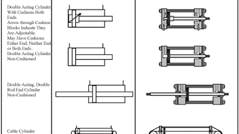
2 position 4 way 5 ported manual general symbol standard double acting.
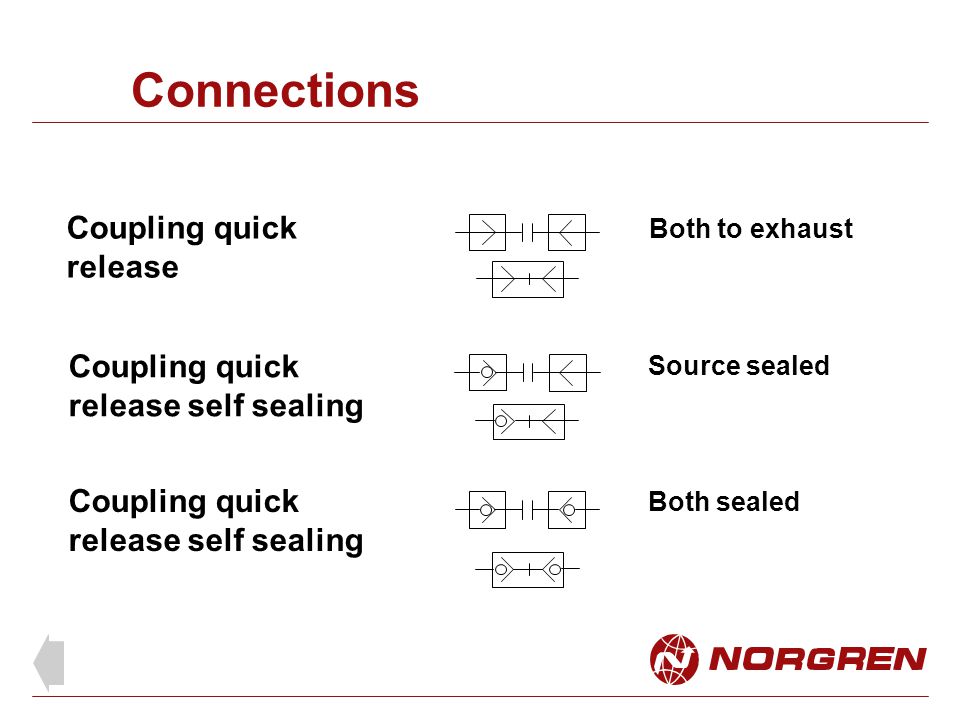
Hydraulic quick connect symbol.
Pneumatic symbols only when the design fails does it draw attention to itself.
Temperature indicators and recorders 9 1 2 and temperature compensation 10 16 3 and 10 16 4.
The vector stencils library fluid power valves contains 93 symbols of pre made hydraulic and pneumatic valves including directional control valves flow control valves pressure control valves and electrohydraulic and electropneumatic valves.
Products solutions samples buy.
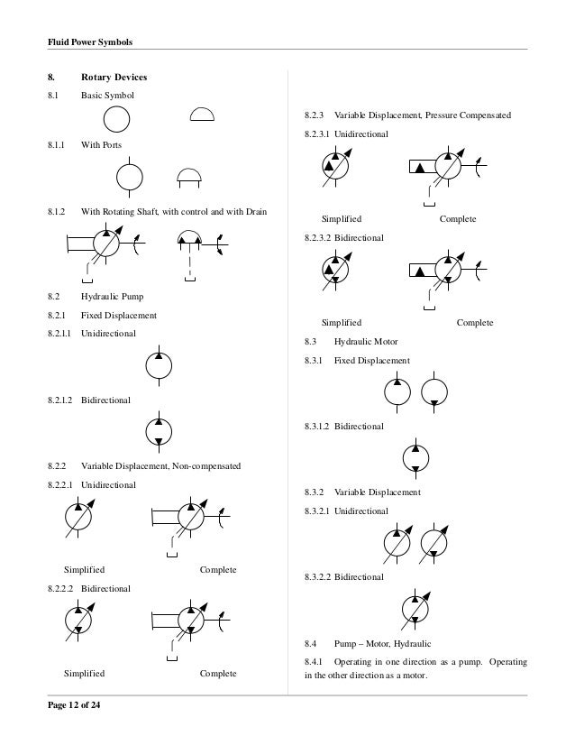
A hydraulic pump converts electrical and or mechanical energy into hydraulic energy.
In such cases look first in the supplier s catalog for the symbol they show.
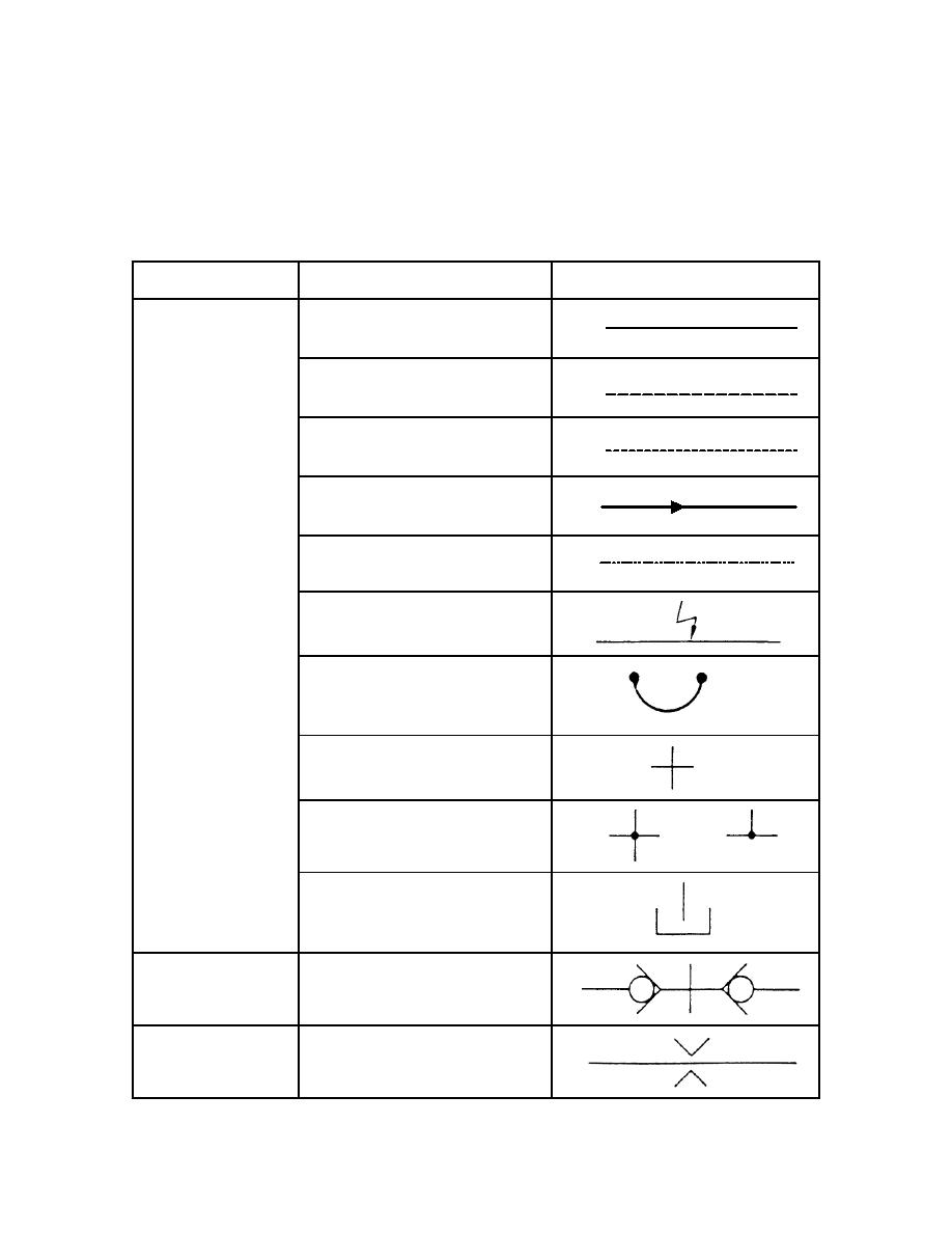
To posltlon quick exhaust shuttle symbol description solenoid internal pilot supply reuote pilot supply md lot n and pilot or manual override pilot lines and functions description une dotted or line center line enclosure outline lines crossing 90.
If the supplier did not make a symbol the only other option is design one for the new part.
When it succeeds it s invisible.
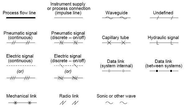
The isa s5 1 iso 10628 and bs 5070 cover the standardization of p id symbols and guide process engineers in their plant design activities.
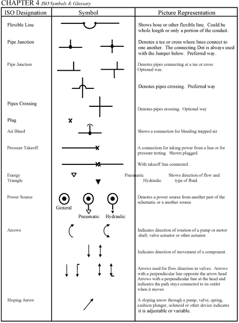
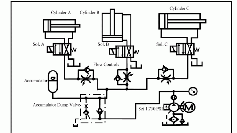
Hydraulic and pneumatic knowledge fluid power equipment the following are iso hydraulic line schematic symbols commonly used on technical drawings.
Hydraulic circuits can be comprised of an infinite combination of cylinders motors valves pumps and other equipment connected via hydraulic pipes and tubes.
The complexity of these components are difficult to represent fully so a family of graphic symbols have been developed to represent fluid power components and systems on schematic drawings.
Scan through and easily download the one you need.
Thermometer is the symbol for temperature cause or effect see temperature controls 7 9.
2 12 external ports are located where flow lines connect to basic symbol except where component.
The dark upper triangle in these hydraulic symbols indicates fluid going out of the system and hence represents a pump.
Try to design the new symbol using standard practices shown here.
The most common p id symbols are listed below.
Hydraulic medium pedal or treadle mechanical cam toggle etc.
As the phrase fluid power implies these symbols cover both hydraulic and pneumatic components.
Hydraulic symbol quick connect.
The lower end suction side of a pump is connected to the hydraulic reservoir the upper end is connected to the remaining circuit.
P id symbols exist for all major components and lines such as valves vessels instruments pumps compressors and towers.
Symbol description 2 position 4 way quick exhaust shuttle 3 position 4 way apb ports closed center pos.