Hydraulic Directional Control Valve Symbols Pdf
Reading Fluids Circuit Diagrams Hydraulic Pneumatic Symbols
Book 2 Chapter 8 Directional Control Valves Hydraulics Pneumatics

China Electrical Operated Directional Control Valve Hydraulic Control Valve Hoyea

Directional Control Valves Symbols Hydraulic Valve
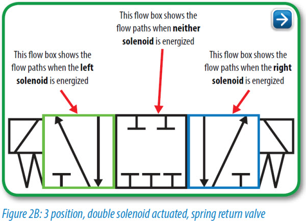
Pneumatic Circuit Symbols Explained Library Automationdirect
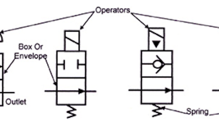
Hydraulic Symbols Introduction

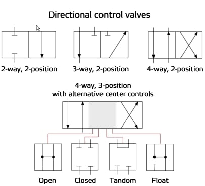
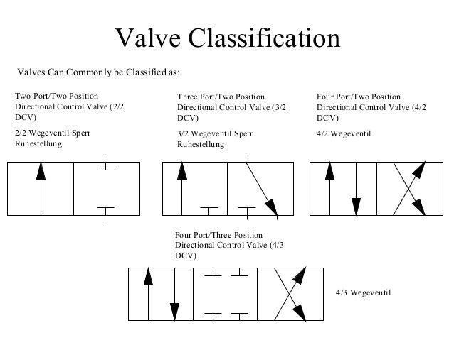
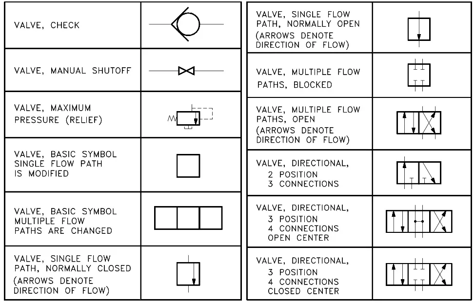
As with all fluid power components directional control valves can be represented by standard symbols published in iso 1219.
Hydraulic directional control valve symbols pdf.

Hydraulic Symbology 201 Industrial Directional Valves
Hydraulic And Pneumatic P Id Diagrams And Schematics Instrumentation Tools

Figure C 2 Hydraulic Schematic Sheet 6 Of 7

Engineering Essentials Directional Control Valves Hydraulics Pneumatics
Source : pinterest.com
