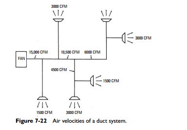
14 2 acoustical analysis of a ductwork system.
Hvac duct design example pdf.
15 4 determining air flow at grilles.
15 6 provisions during design for testing adjusting and balancing.
Example a building 35 feet wide and 73 feet long is constructed with the type of concrete wall indicated in figure 1.
The fibrous glass duct system may be used.
The east and west walls each have two windows.
The concrete is 4 inches thick and the polystyrene insulation is 2 inches thick on each side.
15 5 determining air flow in ducts.
500 pa limits of the fibrous glass duct system.
As an equation this is written.
Duct design fundamentals static pressure ps measure of the static energy of air flowing air which fills a balloon is a good example of static pressure equally exerted in all directions the atmospheric pressure of air is a static pressure 14 696 psi at sea level.
Ductwork testing system performance.
Consequently the total pressure or total energy of air flowing in a duct system is generally equal to the sum of the static pressure and the velocity pressure.
Design cfm 4 cfm 6 cfm 8 cfm 10 cfm 12 60 6x4 60 4x6 90 4x8 120 4x10 150 4x12 90 8x4 110 6x6 160 6x8 215 6x10 270 6x12 120 10x4 160 8x6 230 8x8 310 8x10 400 8x12 150 12x4 215 10x6 310 10x8 430 10x10 550 10x12 180 14x4 270 12x6 400 12x8 550 12x10 680 12x12 210 16x4 320 14x6 490 14x8 670 14x10 800 14x12 240 18x4 375 16x6 580 16x8 800 16x10 950 16x12 270 20x4 430 18x6 670 18x8 930 18x10 1100.
There is a wealth of information available concerning air volume determination heating and cooling loads fan selection and specification.
Treatment may be specified in a single hvac duct system.
The north wall has 6 windows and the south wall has 9 windows.
For example in a variable air volume system sheet metal ducts with fibrous glass duct liner may be used on the high pressure side if design static pressure exceeds the 2 in.
Ductwork design considerations 33 11 1 duct frictional resistance 33 11 2 duct equivalent length 35 11 3 ductwork system effect 35 11 4 installation issues 37 11 5 ductwork insulation 38 11 6 ductwork air leakage 39 11 7 testing methods and equipment 40 11 8 ductwork sealing 41 11 9 volume flow rate measurements 42.
15 3 air flow measurement instruments.
What does exist is difficult to understand.
15 1 balancing the system.
15 2 testing methods and equipment.