Custom resistors and resistor network solutions are also available.
High voltage divider network.
Voltage dividers are one of the most fundamental circuits in electronics.
A voltage divider is a simple circuit which turns a large voltage into a smaller one.
Written by willy mcallister.
Voltage dividers and network resistors.
If we note r series r 1 r 2 r 3 r 4 r 5 the equivalent resistance for the series association of resistors each voltage is given by equation 3.
Metallux high voltage dividers are available as a representative selection of various types.
Various models are produced depending on the application air oil potted etc.
A voltage divider is a simple series resistor circuit.
The divide down ratio is determined by two resistors.
Precision through hole high voltage divider network resistance values available r 1 99 9mω or 99mω to r 2 100kω or 1mω with a total resistance of 100mω absolute tcr of 30 ppm c between 55 c and 125 c and ratio tcr of 25 ppm c or 10 ppm c between 55 c and 125 c.
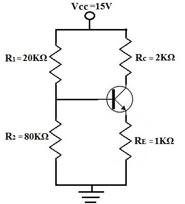
A voltage divider circuit is a very common circuit that takes a higher voltage and converts it to a lower one by using a pair of resistors.
We need to conclude the sections about resistive voltage dividers by saying that.
The product line consists of over 250 models including high voltage resistors current sense resistors chip resistors high frequency resistors rf resistors load resistors pulse resistors and non inductive power resistors.
Using just two series resistors and an input voltage we can create an output voltage that is a fraction of the input.
The high voltage is applied across the divider and the divider output which outputs a lower voltage that is within the meter s input range is measured by the meter.
Thin film center tapped resistors divider network for high temperature applications.
All of our products feature the highest degree of precision and stability.
It s output voltage is a fixed fraction of its input voltage.
Voltages expressions in a voltage divider network.
Networks are based on special application oriented requirements.
For a voltage divider network with n resistors equation 3 remains valid with r series r 1 r 2 r n.
We develop and produce numerous different designs and sizes of voltage dividers.

